Electric Keyboard
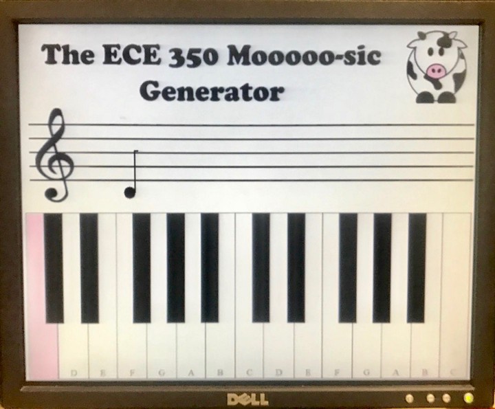 The electric keyboard graphical interface.
Introduction
For the final project for my Digital Systems (ECE350) class, my friend and I created an electric keyboard with 13 custom-made keys using digital logic and an FPGA. The user can play up to three notes simultaneously on a physical light/touch-sensitive keyboard, hear the notes played, and see the notes played on a graphical staff as well as their duration in real time. Each piano key has an LED that lights up when that key is pressed, so the user interacts with a light-sensitive circuit. Additionally, when a key is pressed it sends a signal into our software modules, and in particular our processor. The processor performs computations based on the note played in order to determine how to display that note on a musical staff (how long the note has been played and what note was played). A keyboard key is also highlighted on a graphical keyboard based on the note played. There are also three speaker outputs that play the frequency being sent to them from the clock divider.
Project Specifications
- A breadboard with 13 sensing circuits for piano keys made of photoresistors, transistors, and LEDs that will light up in response to user input and also send a signal to the processor: The signal is interpreted to determine what note is pressed. When the note is processed, a piezoelectric speaker plays the sound. This also involves a clock divider module to send pulses at the correct frequencies to the speakers. The notes are mapped to the button inputs in order to select the proper divided clock frequencies and send them to to an amplifier circuit to play sound from the piezoelectric speaker. The processor handles the I/O from all of the notes, stores them in a register, and uses this info to determine how to respond and display the music notes.
- A custom-designed 3D printed 1-octave piano: This brings the feel of a piano to the circuit, which is important for a good user experience. The print is designed to fit the 13 keys within the dimensions of the breadboard and includes holes for the photo resistors and LEDs to fit through.
- Ability to push up to three piano keys so that the corresponding keys light up on the screen: The physical key lights update in real time as they are played. This allows the user to see what notes he/she is creating by pressing keys.
- Display of the music notes played by up to three keys simultaneously on a graphical staff: The notes update after every eighth note of time for as long as the user plays them (up to a whole note). When a note is initially played, it shows up as an eighth note. As it is played for more eighth notes worth of time, the display changes the note from an eighth note (1 unit of time) to a quarter note (2 units of time) to a dotted quarter note (3 units of time) to a half note (4 units of time) to a dotted half note (6 units of time) to a whole note (8 units time). After eight beats, a new eighth note is drawn in an updated x coordinate. The x coordinate for the next note updates based on how much time has passed since the last note was first played. Thus, as time goes on, the notes move across the staff. When the notes reach the end of the staff, they return to the beginning of the staff. There is a “reset screen” switch to clear all of the notes currently on the screen. The processor takes in all of the signals received from GPIO pins, determines the numbers of the notes played, determines what keys they map to, whether or not the key note length has changed, the coordinates to display the corresponding musical note, and loads and stores the pixel representation and location in memory for the VGA controller (for the display).
Processor Design
As a precursor to this project, I designed a five-stage pipelined single-issue 32-bit processor that supports 18 MIPS instructions. I additionally modified the register file to allow for:
- A clock cycle counter that could be automatically written to, written to from mips, and read from mips
- The ability to process musical note inputs
- The storage of values that a VGA controller could use to update the graphical staff on the screen

Physical Design
We designed the piano key frame using SketchUp and 3D printed the 13-key model.

Underneath the frame lay a breadboard that contained 13 identical sensing circuits, where each circuit was made up of resistors, a photoresistor, a transistor, and a light-emitting diode (LED). The LED stood up through the top hold in each key and the photoresistor stood up through the bottom hole of each key.

A piano key press was simulated by hovering (or touching) a finger over the edge of the key, where the photoresistor was located. We used an IRLD014 NPN MOSFET as a transistor to control when current should flow from its drain to its source, or from the 1K resistor to ground. The photoresistor was connected to the gate of the MOSFET as well as to a 10K resistor that was grounded. When the photoresistor was covered (received less light), its resistance decreased, so there was a lower voltage drop across it (less of a drop from VCC), which caused the gate voltage to increase. As the gate voltage increased, more current flowed from the drain of the MOSFET to the source and since the IR LED was connected to the drain of the MOSFET, more current flowed from VCC (3 volts) through the 1K resistor and into the LED (labeled “TO_DI” or “to diode”). Therefore, covering the photoresistor illuminated the LED and we were able to simulate a key lighting up by hovering a finger over the key.

And here is a demo of the electric keyboard!
Aninda Manocha
Computer Science PhD Student
My research interests lie in hardware-software co-design and memory hierarchy approaches to allow emerging workloads and technology trends to meet in the post-Moore’s Law era.